What Is a Machined Motor Shaft?
A Machined Motor Shaft is a precision-engineered component that transfers rotational power from a motor to connected equipment. It may appear simple, but its performance depends on careful dimensions, material selection, and surface quality. A small error can create vibration, noise, or premature bearing wear.
Manufacturers usually produce these shafts from steel, stainless steel, or other engineered alloys. CNC turning, milling, grinding, and keyway cutting can shape the shaft to demanding specifications. Engineers examine diameter, length, concentricity, hardness, runout, and surface finish before approval. These details matter when the shaft operates at high speed or under repeated loads.
The shaft connects moving parts.
In practical applications, it may drive pumps, fans, conveyors, gearboxes, or industrial automation systems. A reliable Machined Motor Shaft should match the motor’s torque, rotational speed, coupling design, and installation environment. Engineers also consider corrosion, temperature, lubrication, and shock loading. Ignoring one factor can weaken an otherwise excellent design.
Quality control provides confidence, yet no component is perfect. Measurement methods, machine condition, and installation practice can influence results. Therefore, experienced manufacturers combine calibrated inspection tools with process documentation and application-specific testing. This article explains how machined motor shafts are made, selected, inspected, and maintained. It also examines common design mistakes, because real-world failures often begin with assumptions that seemed reasonable.
Definition and Core Function of a Machined Motor Shaft
What Is a Machined Motor Shaft?
Definition and Core Function of a Machined Motor Shaft
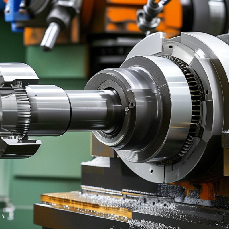
A machined motor shaft is a precision-formed metal component that transfers rotational force from a motor to another moving part. Manufacturers create it by turning, milling, drilling, or grinding metal stock. The finished shaft may include shoulders, keyways, threads, grooves, or precise mounting surfaces. Its core function is simple: transmit torque while maintaining stable, controlled rotation.
In practical motor assemblies, shaft accuracy affects vibration, noise, bearing life, and power delivery. Engineers check diameter, concentricity, straightness, hardness, and surface finish. Even a small dimensional error can produce uneven loading. A shaft may look flawless, yet poor alignment can shorten service life. This is why reliable production includes calibrated measurement tools and documented inspections. Material choice also matters. Steel often provides strength, while stainless alloys can improve corrosion resistance in demanding environments. The correct option depends on load, speed, temperature, and operating conditions.
Tips: Confirm the shaft drawing before production. Measure critical diameters at several points. Check keyways for sharp burrs. Review fit with the bearing and coupling. Do not assume visual inspection is enough. A better question is whether the shaft remains accurate under real operating loads. Testing can reveal weaknesses that machining alone cannot show.
What Is a Machined Motor Shaft? – Definition and Core Function
A machined motor shaft is a precision-manufactured rotating component that transfers torque from a motor to connected parts such as gears, couplings, pulleys, or rotors. The chart shows the theoretical torsional capacity of solid steel shafts with different diameters.
The values are calculated using the solid-shaft torsion relationship T = πτd³ / 16, assuming an allowable shear stress of 40 MPa and no keyways, grooves, or stress concentrations. In practical motor-shaft design, the final capacity also depends on material, fatigue loading, surface finish, machining tolerances, and safety factors.
How a Motor Shaft Is Machined
What Is a Machined Motor Shaft?
How a Motor Shaft Is Machined
A motor shaft begins as round steel, stainless steel, or another specified alloy. The material choice depends on torque, speed, corrosion exposure, and operating temperature. A machinist studies the drawing before cutting anything. Diameters, shoulders, keyways, threads, and runout limits must be understood clearly.
The blank is usually cut slightly oversize. A lathe then removes material while the shaft rotates between centers or in a chuck. The machinist creates bearing journals, steps, and end features with controlled passes. Cutting speed and feed rate affect surface finish and tool wear. Small mistakes can grow quickly. A few extra thousandths of an inch may change bearing fit.
After turning, a milling machine may cut a keyway or a flat. Threads can be machined with a threading tool or formed through another controlled process. Some shafts require heat treatment for strength. Heat can cause distortion, so finish grinding may follow. Grinding brings critical journals closer to their final dimensions.
Inspection is part of the machining process, not an afterthought. Micrometers check diameters, while a dial indicator measures runout. A surface tester may verify journal smoothness. The shaft can look perfect and still fail inspection. I have found that measurement points matter as much as the measuring tool. Temperature, burrs, and cleaning habits can influence readings. Careful work includes checking the drawing again when something feels uncertain.
Common Applications in Motor Systems
What Is a Machined Motor Shaft?
A machined motor shaft is the rotating steel component that transfers torque from a motor to driven equipment. Manufacturers cut, turn, grind, and inspect the shaft to create precise diameters, keyways, threads, splines, and bearing seats. These details control alignment and power transmission. A small surface error can create vibration, heat, or premature bearing wear.
Common Applications in Motor Systems
Machined shafts operate inside pumps, fans, compressors, conveyors, gearboxes, generators, and industrial robots. In a centrifugal pump, the shaft carries torque to the impeller while seals protect the motor system from fluid leakage. Conveyor systems often use keyed or splined shafts for dependable torque transfer under repeated starts and stops. Robotic equipment may require tighter runout control because even slight eccentricity affects positioning accuracy.
The U.S. Department of Energy’s Motor System Market Assessment reports that motor systems consume about 68% of industrial electricity in the United States. The International Energy Agency also estimates that electric motor systems represent roughly half of global electricity use. These figures explain why shaft design influences more than mechanical durability. It can affect efficiency, maintenance frequency, and energy losses across entire facilities.
A shaft may look flawless and still perform poorly. That assumption is risky. Engineers must check material hardness, runout, balance, corrosion exposure, and load cycles. Real installations are rarely perfect. Misalignment, weak lubrication practices, and unexpected overloads can defeat an otherwise accurate machining process. Careful inspection remains essential.